Relationship between CPU and program
About the inside of the CPU
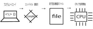
The flow of the created program until it is executed in the computer is as shown below. This is a prerequisite for knowing how the program works.
Here, the CPU is the device that interprets and executes the contents of the program that is finally converted into machine language.
A CPU or memory is an electronic component called an integrated circuit (IC) composed of many transistors, and the interior of a CPU is composed of four elements: a register, a control unit, an arithmetic unit, and a clock. These four elements are electrically connected.
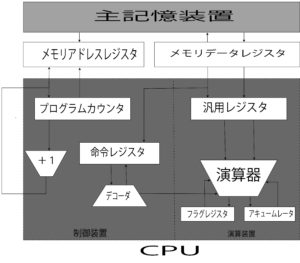
Register”: An area that stores instructions and data to be processed, and works in a similar way to memory. It depends on the type of CPU, but there are about 20 to 100 registers in one CPU.
Control device: The instructions and data in memory are called to registers, and the entire computer is controlled according to the results of instruction execution.
The arithmetic unit: It is responsible for computing the data read from memory to the register.
Clock: The clock signal that generates the timing for the CPU to operate. Some computers have clocks that are outside the CPU.
A “clock signal”, also called a “clock pulse”, is expressed in the frequency: GHz. (1 GHz = 1 billion times per second). The higher the clock frequency, the faster the CPU will run.
Main memory (main memory)
It is connected to the CPU via a control chip, etc., and stores instructions and data in this location. The main memory is made up of readable and writable memory elements, each byte (= 8 bits) is numbered with a number called an address.
The CPU reads and writes instructions and data stored in the main memory by specifying this address. However, the instructions and data stored in the main memory are erased when the PC is powered down due to the volatility of the elements used in the memory.
From the structure of the CPU and memory, when the program starts to run, the controller reads instructions and data from the memory in accordance with the clock signal. By interpreting and executing the instructions, data is computed by the arithmetic unit, and the control unit controls the computer according to the results. Here, control refers to processing other than data arithmetic, and is mainly about managing the timing of data input and output. Input from the keyboard and mouse, as well as output to the display and printer, is also done by “control”.
CPU, which is a collection of registers
Of the four CPU internal elements, the one you must be especially aware of in programming is the “register”. The program is written for this register.
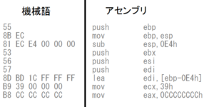
The right side of the above figure is a part of the program written in “assembly language (assembler)”.
Assembly language assigns an English-like abbreviation (mnemonic) to each individual machine language instruction (left-hand side of the figure above), which is essentially an electrical signal, for its behavior; MOV and SUB are abbreviations for the behavior of data storage and data summing, and assembly language and machine language are essentially one-to-one.
This is what sets it apart from high-level languages such as C and Java, and is the main reason why assembly language is better suited to explaining CPU behavior.
The conversion of assembly language to machine language is called assembly, and its disassembly is called disassembly.
Here, the eax and ebp described on the further right side of the assembly item on the right side of the above figure represent the registers, and the corresponding instructions such as push and mov on the left side operate the registers to store and total data.
The one that allocates the procedure of processing data by operating the register inside the CPU according to the instruction of the program converted to the machine language in the above figure to the instruction word that is easy for the human to understand is the assembler language, and the one made it as the language that is easy for the human to describe it further becomes the high-level language (C language, Java, etc.).
In other words, the program can be imagined as indicating the procedure of how the data stored in the main memory is controlled and processed by using the collection of registers in the CPU.
In addition, programming means creating (programming) work procedures for the work you want the computer to do according to the specifications, after understanding the memory and CPU internal structure (registers).
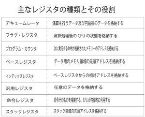
Depending on the type of CPU, the number and type of registers inside the CPU and the size of values that can be stored are also different. The diagram above shows the main types of registers. The values stored in the registers may represent “instruction” and “data,” and there are two types of “data” values: “operation” and “memory address,” and the type of register to be stored differs depending on the type of value. (See figure above.)
The programmer assembles the program with these registers in mind.
The program counter determines the flow of the program.
Now that we have an image of the CPU, we will explain how the program executes as described.
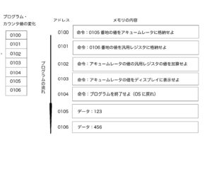
The above figure shows the memory contents when a program is started, and the OS copies the program stored on the HDD to the memory when the user instructs it to start the program. In the above case, the program displays the result of the addition of two values, 123 and 456, on the display.
The memory is assigned an address that indicates where instructions and data are stored. In practice, it is common for a single data or instruction to be stored across multiple addresses, but in the above diagram, for convenience and simplicity, we assume that the instruction or data can be stored at a single address.
Address 0100 is the position of the program start, and OS sets 0100 to the program counter that is one of the registers after copying the program from HDD to the memory. This starts the program execution and automatically increases the position of the program counter by one when the CPU executes one memory.
For example, if the instruction 0100 is executed, the value of the counter will be 0101. (If an instruction that occupies more than one memory address is executed, the counter value is increased by the size of the instruction. The CPU controller reads and executes instructions from memory with reference to the value of the program counter. In other words, the program counter determines the flow of the program.
Conditional branching and repetition
There are three types of program execution flows: sequential progression, conditional branching, and repetition.
Sequential: Execute instructions in the order of address values.
Conditional branching (if): execution of an instruction at an arbitrary address according to a condition.
Repetition (for): Repeating an instruction at the same address several times.
In the case of sequential progression, the value of the counter only increases by one, but in the case of conditional branching and repetition, those machine word instructions will set the value of the program counter to an arbitrary address.
This allows you to go back to the previous address and repeat the same instruction, or move to an arbitrary address and branch out.
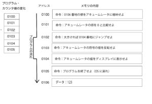
The figure above shows the program that displays the absolute value of the value “123” stored in memory on the display, starting at 0010 and jumping to 0104 if the accumulator value is positive at that time. At this point, the accumulator has a positive value of “123”, so 0103 is skipped and we jump to 0104.
In practice, the command to jump to 0104 is indirectly equivalent to saying, “Set 0104 to the program counter.
A “jump instruction” performed in a conditional branch or repetition refers to the results of the previous operation to determine whether or not to jump. The registers in the CPU that play this role are called “flag registers”. The “flag register” has the role of storing whether the accumulator value is negative, zero or positive as a result of the last operation.
Each time the CPU performs any operation, the value of the flag register is automatically set according to the result. In a conditional branch, some kind of comparison operation is performed before the jump instruction, and the resulting value is referenced by the CPU to determine whether or not to execute the jump instruction.
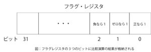
The three bits of the flag register (shown above) indicate which of the three states (positive, zero, or negative) the result of an operation has become. The figure above shows the 32-bit flag register. This register indicates that the 0th, 1st, and 2nd bits are positive, zero, and negative, respectively, by each representing a value of 1.
When the CPU compares the value “A” stored in the accumulator with the value “B” stored in the general-purpose register, when the instruction for comparison is executed, the CPU’s internal arithmetic unit subtracts “A-B” and records the result of the subtraction in the flag register as positive or negative. That is, positive is represented by A>B, zero is represented by A=B, and negative is represented by A<B. The comparison instruction is processed as a subtraction in the CPU.
How to call a function

In a program, the process of calling the function is realized by setting the value of the program counter to the address where the function is stored. However, it is different from the conditional branching and repetition mechanism. The function call should bring the processing flow to the next address of the function caller after the internal processing of the function is completed (see the figure above)
If you set a function at a certain address, the function will be called at the address at the entrance of the function. And when the function is processed, it returns to the next address of the address where the function was first set and gets on the flow of the program again. This means that.
In the above figure, we assign the values 123 and 456 to variables a and b, respectively, and then call the function Myfunk. The address is assumed to be the address when a C program is compiled and converted to machine language, because a one-line C program is often converted to a multi-line machine language, so the address is scattered.
Call Instructions and Stack Instructions
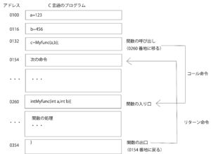
A call instruction is an instruction that calls a function from a specified address, and a return instruction is an instruction that, after the function has been processed, sets the next instruction to be executed at the next address of the function’s caller.
Call Instructions: Before setting the entry address of the function to the program counter, the address of the instruction to be executed next to the call of the function is stored in an area of main memory called the stack. When the function processing is finished, the return instruction is executed at the end of the function (the exit of the function).
The return instruction: This instruction sets the address stored in the stack to the program counter. In the case above, a value of address 0154 is stored on the stack before the Myfunc function is called; when the Myfunc function finishes processing, the value 0154 is read from the stack and set to the program counter.
When the program is compiled, the function call is converted to a call instruction, and when the function processing is finished, the processing is converted to a return instruction.
Image of CPU operation
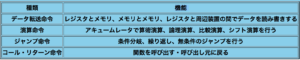
The diagram above shows a broad classification of the machine language instructions used in CPUs. As shown here, the CPU can do surprisingly little, but this combination of instructions is used to process complex programs.
At first glance, the structure of a computer and the CPU may seem difficult, but each one is just a series of simple instructions.